|
|
|
Making the PCBs
The process of making your own printed circuit boards can be divided into the following steps:
- Design the PCB layout
- Print the PCB negative
- Transfer the negative to a light sensitive board
- Develop the board
- Etch the board with ferric chloride
- Clean up
Depending on your temperament, some of these stages are more enjoyable than the others.
To design the layout of the board it is best to use an object based drawing package. There are of course specialist pcb design programs, but they tend to be expensive and complicated to learn. For simple jobs any drawing or art program than can place circles and lines onto a 0.1 inch grid will do the job. I use a program called Draw on a computer system few people have ever heard of and it does the job admirably well.
The next step is to transfer your hopefully faultless design onto a clear acetate sheet. For this the simplest way is to use either a laser printer or an ink-jet printer. Both methods have one serious flaw though. When both types of printer print black areas, they leave hundreds of tiny pinholes where the the ink or the toner have failed to cling onto the surface. When this is transferred to the photosensitive board the resultant pcb looks terrible and is often unusable.
I have found a simple solution to the problem. I use a Canon IP4000 printer and I simply set the print-run to highest paper quality and print the thing twice - one run on top of the previous run. The line-up is usually very good and the printed tracks end up as black and solid as the Duke of Wellington's legendary boots.
In the past, when I was poorer, I used to print the design onto ordinary paper which I then rubbed with olive oil. This made the paper semi-transparent and with 10 to 20 minute exposure time, produced quite good boards. In this day and age this method is of course only good for masochists.
Once you have your negative it is time to cut a suitable size of pre-sensitized photosensitive board. These are covered with a black protective plastic layer, which you should avoid scratching or damaging in any way. I store my boards wrapped in black plastic at the back of a dark cupboard. As they are sensitive to ultra violet light - and daylight consists partly of this frequency - any unnecessary exposure should be avoided. On the right is a group portrait of the cut board and the negative.
After sawing the board make sure to remove any rough edges with a file. This makes sure that contact between the two is as close as possible during the exposure stage.
A word about pre-sensitized boards. Using a good quality board is vital. I've had total disasters after using the same years-old techniques on a different board and no matter what I did, with certain type of boards I could never get a decent result.
 The next step is to transfer the track pattern to the board. I use an ultra violet exposure unit. Peel the black protective film from the board and place the negative onto the board. This is where mistakes can easily be made. If you place the negative the wrong side around, you end up with a mirror image of the intended. circuit which is only fit for the bin. The next step is to transfer the track pattern to the board. I use an ultra violet exposure unit. Peel the black protective film from the board and place the negative onto the board. This is where mistakes can easily be made. If you place the negative the wrong side around, you end up with a mirror image of the intended. circuit which is only fit for the bin.
I always make sure that there is some writing on my pcbs, because that makes it easy to determine correct positioning.
With my set-up, a 2 minute exposure gives perfect results. With other boards I had to use as much as 5 or 10 minutes. A few experiments will quickly determine the correct timing.
 Above can be seen the negative in contact with the board and on the right is the board after exposure. Above can be seen the negative in contact with the board and on the right is the board after exposure.
Notice the very faint greenish lines. If you can see those, all is well.
|
 The next step is the preparation of the developer. Exact quantities are not critical I use slightly more than a level teaspoon full of caustic soda to half a litre (500ml) of tap water. Do not heat the water. Stir the mixture well until all the crystals have been desolved and empty the solution into a developing dish - in my case and old sandwich box. The next step is the preparation of the developer. Exact quantities are not critical I use slightly more than a level teaspoon full of caustic soda to half a litre (500ml) of tap water. Do not heat the water. Stir the mixture well until all the crystals have been desolved and empty the solution into a developing dish - in my case and old sandwich box.
|
 Place the board into the solution copper side up and agitate by rocking the dish. After a few seconds the surface of the board will discolour, as the light sensitive layer dissolves in all the places that the ultra violet light softened. Place the board into the solution copper side up and agitate by rocking the dish. After a few seconds the surface of the board will discolour, as the light sensitive layer dissolves in all the places that the ultra violet light softened.
Development should be finished after about a minute or two. The time depends on the strength of the solution, its temperature and for all I know the length of exposure. If things have gone wrong, this is the stage where this will become apparent. One extreme is that nothing dissolves no matter how long you rock the dish, the other extreme is that all your hard work dissolves in front of your very eyes in a few sad seconds and leaves you with a wonderfully blank copper-clad board.
If things look the way they look in my photograph, you are on to a winner.
 As caustic soda can be used as drain cleaner, the left-over solution can be carefully discarded into any blocked drain you might have in the house. Careful though, it is a very strong solution and rubber gloves might be a good idea. On the left you can see the finished board. Nice sharp lines and good fine detail are visible. As caustic soda can be used as drain cleaner, the left-over solution can be carefully discarded into any blocked drain you might have in the house. Careful though, it is a very strong solution and rubber gloves might be a good idea. On the left you can see the finished board. Nice sharp lines and good fine detail are visible.
It helps to examine the board carefully at this stage. If you detect any spots caused by dust, they can be removed by scratching. If there are accidental holes in any of the tracks, they can be touched up with an etch resist pen.
|
 We are now ready to etch the board. My set-up is on the right. A small dish containing ferric chloride sits in a larger dish with boiling hot water. The somewhat archaic looking set-up is completed by a geared motor and an old ZX80 power supply. The action of the motor rocks the dish up and down, thereby assuring a good agitation of the ferric chloride. We are now ready to etch the board. My set-up is on the right. A small dish containing ferric chloride sits in a larger dish with boiling hot water. The somewhat archaic looking set-up is completed by a geared motor and an old ZX80 power supply. The action of the motor rocks the dish up and down, thereby assuring a good agitation of the ferric chloride.
I used to have a photographic darkroom and have adapted some of the techniques I learned in the past to the present problem. If you lack the mechanical equipment, you have to rock the dish by hand. This can be quite boring, because depending on the strength of the ferric chloride solution and on how much copper has been dissolved by it already, development can take anything between 15 and 60 minutes. If it takes longer than this, discard the solution in an environmentally friendly way. Hints on how to do this can be found on the web.
|
 This is how the board looked after about 5 minutes in the solution. Notice that the copper on one edge has already been dissolved. This is how the board looked after about 5 minutes in the solution. Notice that the copper on one edge has already been dissolved.
|
 Here is the board after about 20 minutes. Nearly all the copper is gone and another 2 or three minutes will finish the job. Here is the board after about 20 minutes. Nearly all the copper is gone and another 2 or three minutes will finish the job.
|
 We are nearly done. Check the pcb to make sure that no unwanted copper remains - particularly inside the small drill holes and then wash both sides of the board under a running water tap. We are nearly done. Check the pcb to make sure that no unwanted copper remains - particularly inside the small drill holes and then wash both sides of the board under a running water tap.
A word of warning. If - like me - you use a stainless steel sink, rinse it carefully. Ferric chloride will etch stainless steel as cheerfully as copper. Hence - unless you wash all traces away - your sink may turn into a sieve in a very short time.
|
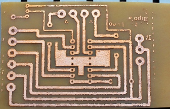
The job is done and it's time to clean up - my favourite task. The finished board is below on the left. The copper tracks are still covered with etch-resist dye. Do not remove. The thin layer protects the tracks from oxidisation and the coating does not prevent soldering. Quite the opposite, it seems to act as a flux.
On the right is a board made with the same procedure but bought from another firm. Notice the moth eaten appearance and rough edges. I tried every trick in the book to get these boards to work but to no avail.
|
|

|
A final word about the ferric chloride solution. After some research on the web I found a page describing a method called the Edinburgh etch. This consists of 4/5 saturated ferric chloride solution and 1/5 of citric acid solution. The latter consists of 3/4 tap water and 1/4 citric acid powder.
I have only started using this method recently, but it seems to be a great improvement. The solution lasts longer and when exhausted, is much more environmentally friendly than ordinary spent ferric chloride.
|
:: بازدید از این مطلب : 639
|
امتیاز مطلب : 0
|
تعداد امتیازدهندگان : 0
|
مجموع امتیاز : 0
ن : circuit
ت : پنجشنبه 05 تیر 1393
|
|
|
|
|


 عضو شوید
 عضویت سریع
 آمار مطالب
 آمار بازدید

