DRIVING A RELAY Circuit - مدار درایور رله با آی سی 555
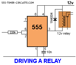
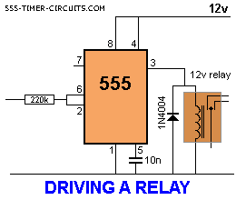
The 555 will activate a relay. When pins 2 and 6 are connected as an input, the
chip requires only about 1uA to activate the output. This is equivalent to a
gain of about 200,000,000 (200 million) and represents about 4 stages of
amplification via transistors.
In the first circuit, the output will be
opposite to the input. The relay can be connected "high" or "low" as show in the
second diagram. One point to note: The input must be higher than 2/3V for the
output to be low and below 1/3V for the output to be high. This is called
HYSTERESIS and prevents any noise on the input creating "relay
chatter."
NEGATIVE LOGIC
An interesting point to
remember.
In the first diagram above, the relay is connected so that it is
active when the output is low. This is called NEGATIVE or NEGATIVE LOGIC. It has
the same reasoning as-5 - (-5) = 0.
Or in English: "I am not NOT going."
When the input is low in
the first diagram, the output is HIGH and the relay is OFF. The circuitry
creates two reversals and makes it easy to see that when the input is LOW, the
relay is OFF.
:: بازدید از این مطلب : 2193
|
امتیاز مطلب : 46
|
تعداد امتیازدهندگان : 12
|
مجموع امتیاز : 12


 عضو شوید
 عضویت سریع
 آمار مطالب
 آمار بازدید

