Capacitance
This is a measure of a capacitor's ability to store charge. A large capacitance means that more charge can be stored. Capacitance is measured in farads, symbol F. However 1F is very large, so prefixes are used to show the smaller values.
Three prefixes (multipliers) are used, µ (micro), n (nano) and p (pico):
- µ means 10-6 (millionth), so 1000000µF = 1F
- n means 10-9 (thousand-millionth), so 1000nF = 1µF
- p means 10-12 (million-millionth), so 1000pF = 1nF
Capacitor values can be very difficult to find because there are many types of capacitor with different labelling systems!
Polarised capacitors (large values, 1µF +)
Examples: Circuit symbol: 
Electrolytic Capacitors
Electrolytic capacitors are polarised and they must be connected the correct way round, at least one of their leads will be marked + or -. They are not damaged by heat when soldering.
There are two designs of electrolytic capacitors; axial where the leads are attached to each end (220µF in picture) and radial where both leads are at the same end (10µF in picture). Radial capacitors tend to be a little smaller and they stand upright on the circuit board.
It is easy to find the value of electrolytic capacitors because they are clearly printed with their capacitance and voltage rating. The voltage rating can be quite low (6V for example) and it should always be checked when selecting an electrolytic capacitor. If the project parts list does not specify a voltage, choose a capacitor with a rating which is greater than the project's power supply voltage. 25V is a sensible minimum for most battery circuits.
Tantalum Bead Capacitors
Tantalum bead capacitors are polarised and have low voltage ratings like electrolytic capacitors. They are expensive but very small, so they are used where a large capacitance is needed in a small size.
Modern tantalum bead capacitors are printed with their capacitance, voltage and polarity in full. However older ones use a colour-code system which has two stripes (for the two digits) and a spot of colour for the number of zeros to give the value in µF. The standard colour code is used, but for the spot, grey is used to mean × 0.01 and white means × 0.1 so that values of less than 10µF can be shown. A third colour stripe near the leads shows the voltage (yellow 6.3V, black 10V, green 16V, blue 20V, grey 25V, white 30V, pink 35V). The positive (+) lead is to the right when the spot is facing you: 'when the spot is in sight, the positive is to the right'. 
For example: blue, grey, black spot means 68µF For example: blue, grey, white spot means 6.8µF For example: blue, grey, grey spot means 0.68µF
Unpolarised capacitors (small values, up to 1µF)
Examples:  Circuit symbol:
Small value capacitors are unpolarised and may be connected either way round. They are not damaged by heat when soldering, except for one unusual type (polystyrene). They have high voltage ratings of at least 50V, usually 250V or so. It can be difficult to find the values of these small capacitors because there are many types of them and several different labelling systems!
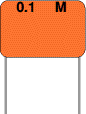 Many small value capacitors have their value printed but without a multiplier, so you need to use experience to work out what the multiplier should be!
For example 0.1 means 0.1µF = 100nF.
Sometimes the multiplier is used in place of the decimal point: For example: 4n7 means 4.7nF.
Capacitor Number Code
A number code is often used on small capacitors where printing is difficult: 
- the 1st number is the 1st digit,
- the 2nd number is the 2nd digit,
- the 3rd number is the number of zeros to give the capacitance in pF.
- Ignore any letters - they just indicate tolerance and voltage rating.
For example: 102 means 1000pF = 1nF (not 102pF!)
For example: 472J means 4700pF = 4.7nF (J means 5% tolerance).
| Colour Code |
| Colour |
Number |
| Black |
0 |
| Brown |
1 |
| Red |
2 |
| Orange |
3 |
| Yellow |
4 |
| Green |
5 |
| Blue |
6 |
| Violet |
7 |
| Grey |
8 |
| White |
9 |
Capacitor Colour Code
A colour code was used on polyester capacitors for many years. It is now obsolete, but of course there are many still around. The colours should be read like the resistor code, the top three colour bands giving the value in pF. Ignore the 4th band (tolerance) and 5th band (voltage rating). 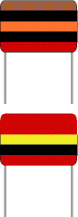
For example:
brown, black, orange means 10000pF = 10nF = 0.01µF.
Note that there are no gaps between the colour bands, so 2 identical bands actually appear as a wide band.
For example:
wide red, yellow means 220nF = 0.22µF.
Polystyrene Capacitors
 This type is rarely used now. Their value (in pF) is normally printed without units. Polystyrene capacitors can be damaged by heat when soldering (it melts the polystyrene!) so you should use a heat sink (such as a crocodile clip). Clip the heat sink to the lead between the capacitor and the joint.
Real capacitor values (the E3 and E6 series)
You may have noticed that capacitors are not available with every possible value, for example 22µF and 47µF are readily available, but 25µF and 50µF are not!
Why is this? Imagine that you decided to make capacitors every 10µF giving 10, 20, 30, 40, 50 and so on. That seems fine, but what happens when you reach 1000? It would be pointless to make 1000, 1010, 1020, 1030 and so on because for these values 10 is a very small difference, too small to be noticeable in most circuits and capacitors cannot be made with that accuracy.
To produce a sensible range of capacitor values you need to increase the size of the 'step' as the value increases. The standard capacitor values are based on this idea and they form a series which follows the same pattern for every multiple of ten.
The E3 series (3 values for each multiple of ten) 10, 22, 47, ... then it continues 100, 220, 470, 1000, 2200, 4700, 10000 etc. Notice how the step size increases as the value increases (values roughly double each time).
The E6 series (6 values for each multiple of ten) 10, 15, 22, 33, 47, 68, ... then it continues 100, 150, 220, 330, 470, 680, 1000 etc. Notice how this is the E3 series with an extra value in the gaps.
The E3 series is the one most frequently used for capacitors because many types cannot be made with very accurate values.
Variable capacitors
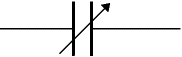
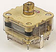
Variable capacitors are mostly used in radio tuning circuits and they are sometimes called 'tuning capacitors'. They have very small capacitance values, typically between 100pF and 500pF (100pF = 0.0001µF). The type illustrated usually has trimmers built in (for making small adjustments - see below) as well as the main variable capacitor.
Many variable capacitors have very short spindles which are not suitable for the standard knobs used for variable resistors and rotary switches. It would be wise to check that a suitable knob is available before ordering a variable capacitor.
Variable capacitors are not normally used in timing circuits because their capacitance is too small to be practical and the range of values available is very limited. Instead timing circuits use a fixed capacitor and a variable resistor if it is necessary to vary the time period.
Trimmer capacitors
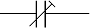
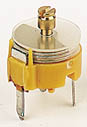
Trimmer capacitors (trimmers) are miniature variable capacitors. They are designed to be mounted directly onto the circuit board and adjusted only when the circuit is built.
A small screwdriver or similar tool is required to adjust trimmers. The process of adjusting them requires patience because the presence of your hand and the tool will slightly change the capacitance of the circuit in the region of the trimmer!
Trimmer capacitors are only available with very small capacitances, normally less than 100pF. It is impossible to reduce their capacitance to zero, so they are usually specified by their minimum and maximum values, for example 2-10pF.
Trimmers are the capacitor equivalent of presets which are miniature variable resistors.
:: بازدید از این مطلب : 1373
|
امتیاز مطلب : 6
|
تعداد امتیازدهندگان : 2
|
مجموع امتیاز : 2


 عضو شوید
 عضویت سریع
 آمار مطالب
 آمار بازدید